# V-blender Simulation (phasicFlow v-1.0)
This tutorial demonstrates the simulation of a V-blender, a common mixing device used in pharmaceutical and powder processing industries. The V-blender consists of a V-shaped vessel that rotates around a horizontal axis, allowing for efficient mixing of particulate materials.
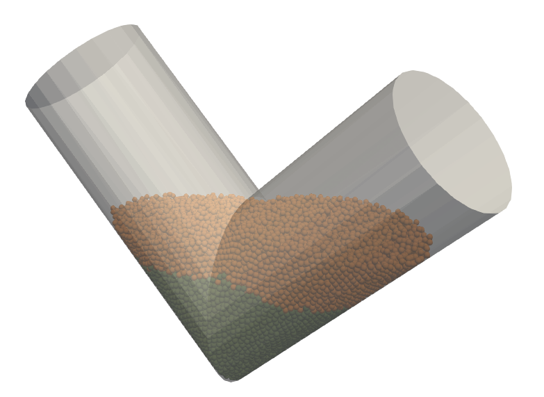
V-blender simulation with two layers of particles
## Problem Definition
The simulation represents a V-blender with the following characteristics:
- The blender is initially empty and is filled with two different particle types in sequence
- First layer: Small particles (10 mm diameter) are inserted from the right side
- Second layer: Slightly larger particles (10.1 mm diameter) are inserted from the left side
- The blender begins rotation at t = 3.0 s and continues until t = 10.0 s
- The rotation speed is set to 3.14 rad/s (approximately 0.5 Hz or 30 RPM)
- The simulation runs for a total of 10 seconds
## Case Setup
The simulation case setup files are organized in the `settings/` and `caseSetup/` folders.
### Particles Definition
Two particle types are defined in the `caseSetup/shapes` file:
```C++
names (smallSphere largeSphere); // names of particles
diameters (0.01 0.0101); // diameter of particles (m)
materials (lightMat lightMat); // material names for particles
```
Both particle types share the same material properties but differ slightly in size to allow for visual distinction during mixing.
### Particle Insertion
Particles are inserted in two sequential phases, as defined in `caseSetup/particleInsertion`:
```C++
active Yes; // is insertion active -> Yes or No
rightregion
{
timeControl simulationTime; // Controls insertion based on simulation time
regionType cylinder; // Defines a cylindrical insertion region
rate 10000; // Inserts 10,000 particles per second
startTime 0.0; // Starts inserting at t = 0s (beginning of simulation)
endTime 1.0; // Stops inserting at t = 1s
insertionInterval 0.025; // Inserts particles every 0.025s
// (40 insertion events during the 1s period)
cylinderInfo {
// Defines cylinder endpoints and radius
p1 (0.0950615 0.12 0.5011585); // First endpoint coordinates (x,y,z) in meters
p2 (0.1150615 0.12 0.4811585); // Second endpoint coordinates (x,y,z) in meters
radius 0.1; // Cylinder radius in meters
}
setFields {
// Initial properties for inserted particles
velocity realx3 (1.2 0.0 -1.2); // Initial velocity vector (x,y,z) in m/s
// Particles move to the right and downward
}
mixture {
// Particle type distribution
smallSphere 1; // 100% of inserted particles are "smallSphere" type
}
}
leftregion
{
timeControl simulationTime; // Controls insertion based on simulation time
regionType cylinder; // Defines a cylindrical insertion region
rate 10000; // Inserts 10,000 particles per second
startTime 1.5; // Starts inserting at t = 1.5s
// (after the first insertion phase)
endTime 2.5; // Stops inserting at t = 2.5s
insertionInterval 0.025; // Inserts particles every 0.025s
// (40 insertion events during the 1s period)
cylinderInfo {
// Defines cylinder endpoints and radius
p1 (0.7562545 0.12 0.50079); // First endpoint coordinates (x,y,z) in meters
p2 (0.7362545 0.12 0.48079); // Second endpoint coordinates (x,y,z) in meters
radius 0.1; // Cylinder radius in meters
}
setFields {
// Initial properties for inserted particles
velocity realx3 (-1.2 0.0 -1.2); // Initial velocity vector (x,y,z) in m/s
// Particles move to the left and downward
}
mixture {
// Particle type distribution
largeSphere 1; // 100% of inserted particles are "largeSphere" type
}
}
```
#### Detailed Explanation of Insertion Parameters
1. **`rightregion` Dictionary**:
- Creates a cylindrical insertion region on the right side of the V-blender
- Active during t=0s to t=1s at the beginning of the simulation
- Particles are inserted from randomly generated positions within the cylinder
- Inserts "smallSphere" particles with 10mm diameter
- Initial velocity (1.2, 0.0, -1.2) m/s directs particles toward the center and bottom of the blender
- 40 insertion events occur (every 0.025s), each adding approximately 250 particles
2. **`leftregion` Dictionary**:
- Creates a symmetrical cylindrical insertion region on the left side of the V-blender
- Active during t=1.5s to t=2.5s, after the first batch of particles has settled
- Inserts "largeSphere" particles with 10.1mm diameter
- Initial velocity (-1.2, 0.0, -1.2) m/s directs particles toward the center and bottom of the blender
- Mirror image of the first insertion but with slightly larger particles
3. **Insertion Region Selection**:
- Cylindrical insertion regions are positioned above each arm of the V-blender
- This arrangement ensures particles fall naturally into the V-blender without initial overlap
4. **Timing Strategy**:
- Sequential insertion with a 0.5s gap between phases allows the first batch to settle
- All particles settle for 0.5s after the second insertion (t=2.5s to t=3.0s)
- Blender rotation begins after all particles have settled (t=3.0s)
### Geometry and Motion
The V-blender geometry is defined in `settings/geometryDict` using an STL file:
```C++
motionModel rotatingAxis; // motion model: rotating object around an axis
rotatingAxisInfo // information for rotatingAxis motion model
{
rotAxis
{
p1 (0.128228 0.116446 0.297901); // first point for the axis of rotation
p2 (0.722596 0.116459 0.297901); // second point for the axis of rotation
omega 3.14; // rotation speed (rad/s)
startTime 3; // start time of rotation
endTime 10; // end time of rotation
}
}
```
The blender starts rotating at t = 3.0 s, after both particle types have been inserted and allowed to settle.
### Simulation Domain and Boundaries
The simulation domain is defined in `settings/domainDict`:
```C++
globalBox
{
min (-0.1 -0.4 0); // lower corner point of the box
max (0.86 0.6 0.6); // upper corner point of the box
}
```
All boundaries are set to "exit" type, meaning particles that go outside the domain will be deleted.
### Particle Interaction Properties
Material properties and interaction parameters are defined in `caseSetup/interaction`:
```C++
materials (wallMat lightMat); // a list of materials names
densities (1000 1000); // density of materials [kg/m3]
// Contact force models
model
{
contactForceModel nonLinearNonLimited;
rollingFrictionModel normal;
// Material properties
Yeff (1.0e6 1.0e6
1.0e6); // Young modulus [Pa]
Geff (0.8e6 0.8e6
0.8e6); // Shear modulus [Pa]
nu (0.25 0.25
0.25); // Poisson's ratio [-]
en (0.97 0.85
0.97); // coefficient of normal restitution
mu (0.65 0.35
0.65); // dynamic friction
mur (0.1 0.1
0.1); // rolling friction
}
```
## Running the Simulation
To run this simulation, execute the following commands in sequence:
1. First, create the geometry:
```
geometryPhasicFlow
```
2. Next, initialize the particle system (note: starts with zero particles):
```
particlesPhasicFlow
```
3. Finally, run the simulation:
```
sphereGranFlow
```
The simulation will automatically insert particles according to the defined schedule and begin rotating the V-blender at the specified time.
## Visualizing Results
After the simulation completes, you can convert the results to VTK format for visualization:
```
pFlowToVTK --binary
```
The VTK files will be stored in a new directory called `./VTK` and can be visualized using tools like ParaView or VisIt.
## Expected Behavior
During the simulation, you should observe:
1. Initial filling with small particles from the right side (0-1s)
2. A brief settling period (1-1.5s)
3. Filling with large particles from the left side (1.5-2.5s)
4. Another settling period (2.5-3s)
5. Rotation of the V-blender causing mixing of the two particle types (3-10s)